
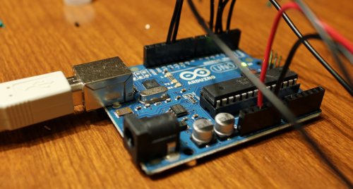
JimM got me interested in Arduinos. They are simple electronics boards that contain almost everything you need to get started with your project. When it arrived in the mail, I connected it to the computer via USB, opened up the development environment, uploaded a small program to the board and boom, I had a blinking light. Simple, yes, but the time to results was extremely low.
My overall plan was to build a display for the Media Center PC in our living room. I wanted to be able to easily see when it was recording something or when one of the tuners was being used by one of the extenders. There are some premade solutions that would have probably worked, but this seemed like a great starter Arduino project and I would end up with something that was completely customizable.
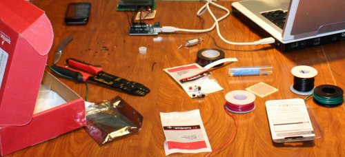
In addition to the Arduino, I got a 20×4 character LCD screen and some small supplies like resistors, wire, buttons, and a potentiometer. This is the point where I should show a schematic for the whole thing, but honestly I never drew one. I built little portions of it as I went and ended up with something that works and hasn’t burned down the house yet.
Basically, the Arduino Uno sends power to the LCD and a 10K potentiometer controls the contrast of the screen. The board also sends the text for the screen through four wires along with a couple extra wires for enabling the screen, etc. The board powers the backlight for the LCD but I hooked up a resistor there to dim the backlight a bit. I had originally planned to have the backlight be controllable from software but I gave up after a couple failures trying to get a transistor hooked into the circuit. There is also a simple button hooked in, but I haven’t needed to use that in the software yet.
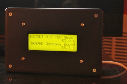
Once I got it all soldered together, I stuck it into a plastic hobby box from Radio Shack. I had to cut out a rectangular hole in the front for the LCD. That was done freehand with a Dremel and looks pretty bad when you get up close. Luckily it hides in the shadows and you can’t really tell. I have ideas to do that better next time.
The box now sits by the Media Center and is connected to the PC via USB. That cable provides power and communications. A C# application gathers status from the Ceton InfiniTV tuner and sets the display for the LCD in the box. (For the curious, there is a JSON interface to get to the InfiniTV status.) When a tuner is in use, the box displays the channel call sign and the name of the show that is being recorded. I get that info by mapping the channel number from the tuner to a call sign and then looking for the corresponding file in the Recorded TV folder. That file has the show name. When a tuner isn’t in use, it shows the temperature of that tuner. I’ll probably come up with something better for unused tuners in the future.
This was my first real electronics project so I learned quite a few things that are probably obvious to other people:
- Use a bread board. Soldering everything to see if it worked was a pain.
- Use header pins so you don’t have to solder directly to the LCD screen.
- This whole thing could have been done in a couple minutes by buying a pre-made LCD shield that plugs in on top of the Arduino. I’m glad I did it manually the first time, but next time I’ll probably go for the shield.
- Buy an introductory electronics book.
- Take more pictures along the way! I was so excited to get this working that it somehow slipped my mind.
What’s next? I have quite a few project ideas but I think the one I’ll tackle next is making a tilt/pan mount for my camera that is controlled by an Arduino and will automatically take big panorama pictures. I’m also going to build an intervalometer into it for time lapse. This project will involve more buttons, motor control, and power from a battery.