If you saw my OneNote page for project ideas, you’d find a multi-year section with ideas for some kind of custom LED installation. My goal was to have every LED be individually addressable so I could make color patterns.
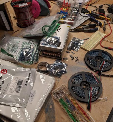
A couple of months ago, I was watching the weekly “Maker Update” video which shows interest projects going on in the maker community and was turned on to this LED wall project by Tech Random. Price has always been a major breaking point for me in the past when I’ve researched this along with confusion about exactly what kind of power supply I need. This project looked good enough to follow so I gave it a shot. All the materials and instructions are in that link so if you’re interested in doing it yourself, I recommend you use that as your shopping list.
If you read the link to the project above, you’ll see all the steps that I followed, but basically it consisted of the following:
- I 3D printed a bunch of grids where each cell was perfectly sized to the spacing of the specific LED strips that I bought. I had to adjust the provided STL files to fit into my smaller printer. I ended up making 4×4 grids because that fit easily on my printer and tiled nicely into my 36×16 panel size.
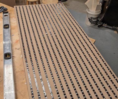
- The four LED strips that I purchased got cut down into strips of 36 lights and laid across a piece of cardboard. In retrospect, I wish I would have glued down some aluminum foil and then put the lights on top. That would have increased reflectivity and provided a little fire protection.
- Each strip has positive, negative, and data wires and I had to solder connections between each wire in a snake pattern across all 16 strips. That was almost 100 solder joints but thankfully they all worked.
- I bought ESP8266 boards to be the drive the display. I had never worked with these before, but they were amazingly powerful for only a few bucks each. Their main feature is that they have a WiFi chip built in. One of those boards got hooked up to the start of the panel and I was able to make a light move through all the lights in the strip.
- Those boards couldn’t provide enough power for the whole strip though, so I used a 5v power supply to inject power at three points along the panel. This resulted in even power distribution across the panel so the colors looked the same in each LED.
- The grids got hot glued on top of the LED strips and then a layer of diffuser cloth was upholstered on as well.
The software for this was a challenge. The project page includes some programs for the ESP8266 boards as well as a custom version of LMCSHD. The original design is that LMCSHD does the calculations for displaying whatever you want onto a grid of any size. Then it sends individual pixel instructions over a COM port (USB) to an ESP8266 which sends it over WiFi to another ESP8266 which is connected to the panel. I got that to work ok, but as I was debugging some issues with frame rate, I realized that I could simplify things if I just made the LMCSHD program talk over WiFi directly to the ESP8266 on the panel. I forked my own copy and got it working.
So at this point, I have a panel sitting behind my desk that plugs in for power but communicates wirelessly with an app that I run on my desktop to feed data to it. The frame rate is good for my purpose, but it still feels a little clunky to get set up and occasionally, the panel stops updating. I think I’m going to work on a simplified console app that sends some pre-programmed patterns to the panel and that’s probably what I’ll use most often.
“Use most often.” What does that mean? I don’t know. I can see it being a fun gimmick on some video calls or maybe I’ll get around to making a second panel and putting both in my front window for Christmas decorations. But even if it doesn’t get used a ton, I’m glad I built it because it has been a fun learning experience and it’s one of those things that I can continue to tinker with.